Actual usage scenario of this switch
This manageable switch has many 2.5G Multigigabit ports with PoE+ support, this is ideal for connecting one or more high-end professional WiFi access points, which are usually dual-band simultaneous with WiFi 6 and have a 2.5G port to not have a bottleneck in the wired network. Of course, we can also have a NAS server with dual SFP+ ports at 10Gbps, to transfer a large amount of data through the local wired network, and even video surveillance IP cameras connected to the switch, and all the video goes directly to the server. NAS that will act like an NVR, but with much more functionality. Next, we are going to show you what we have connected to the managed switch and what configurations we have made.
APs with WiFi 6 and 2.5G port
Any manufacturer of high-performance WiFi 6 access points have 2.5G Multigigabit ports, to avoid bottlenecks due to the wired network. When we have a simultaneous dual-band AP higher than the AX1800 class, they usually have this type of ultra-fast ports so as not to have real WiFi speed problems. In addition, this type of high-end WiFi APs usually need PoE+ since their consumption at full capacity can exceed 15W of the PoE standard.
We have connected a total of 4 WiFi 6 access points with 2.5G port to the ports 8, 9, 10 and 11 of the managed switch. Of course, we have several SSIDs configured and associated to different VLANs, for this reason, we have also created different VLANs for different uses, specifically we have VLAN 10, 11, 13 and 15, which we have to configure in the VLANs part. We will configure these access points so that they are only available during business hours, from 8:00 a.m. to 8:00 p.m., the rest of the time they will be turned off.
IP video surveillance cameras
We have also connected a total of two video surveillance IP cameras in 2K and 4K resolution respectively, these cameras also use PoE+ for power, although in this case the speed of the links is only 100Mbps, because we do not have a higher bitrate to this, so it doesn’t make sense to have Gigabit Ethernet interfaces. In this case we have connected the IP cameras to ports 6 and 7, and configured in VLAN ID 10.
Of course, in this case the video surveillance camera will always be on, so we have not programmed the PoE to turn it on and off automatically, they will always be in operation recording to a NAS server that is connected to port 5 and that is exclusively in charge of video surveillance.
connected PCs
In ports 12 and 13 we have connected a couple of computers and both belong to VLAN 13, which is that of the normal equipment, in port 12 we do not have any type of bandwidth limitation, but we wanted port 13 to be have bandwidth limitation to 600Mbps symmetrical against the local network.
In ports 14-16 we have the ports that are specifically configured for VLAN 15 which is a guest network, in this case we also have bandwidth limitation, the equipment that we connect in port 14 will have 600Mbps symmetrical, but those connected in 15-16 they will only have symmetrical 300Mbps of bandwidth, that is, we are limiting the speed of the local network.
Once we have seen the test scenario, we are going to configure this managed switch with the requirements that we have indicated previously.
How to configure this managed switch
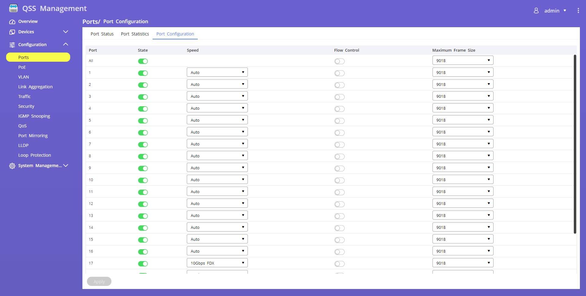
The first thing we must do is enter the manageable switch through the IP address provided by the DHCP server, otherwise, we can always access via the web with the default IP. Once we are inside, the first thing we must do is verify that the physical switch ports are enabled, with speed set to auto, and that Jumbo Frames are set appropriately. This is the default configuration of the device, so you should have this configuration as it is below:
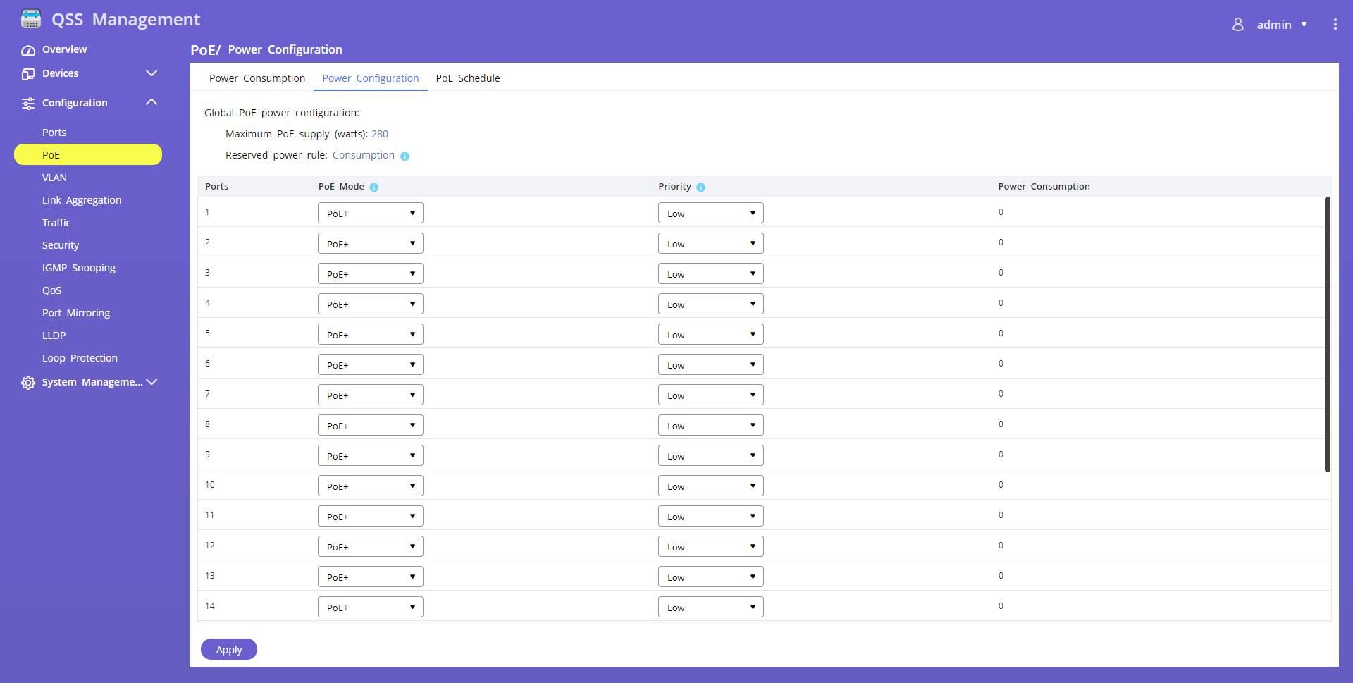
In the PoE section we have to make sure that we have PoE+ mode on all ports. In this case, we can configure the priority in case we go over 280W, however, in our case it was not necessary because we did not get there. In case we are close to 250W, our recommendation is that you give high priority to the IP cameras, and the rest of the devices with the default “Low” priority.
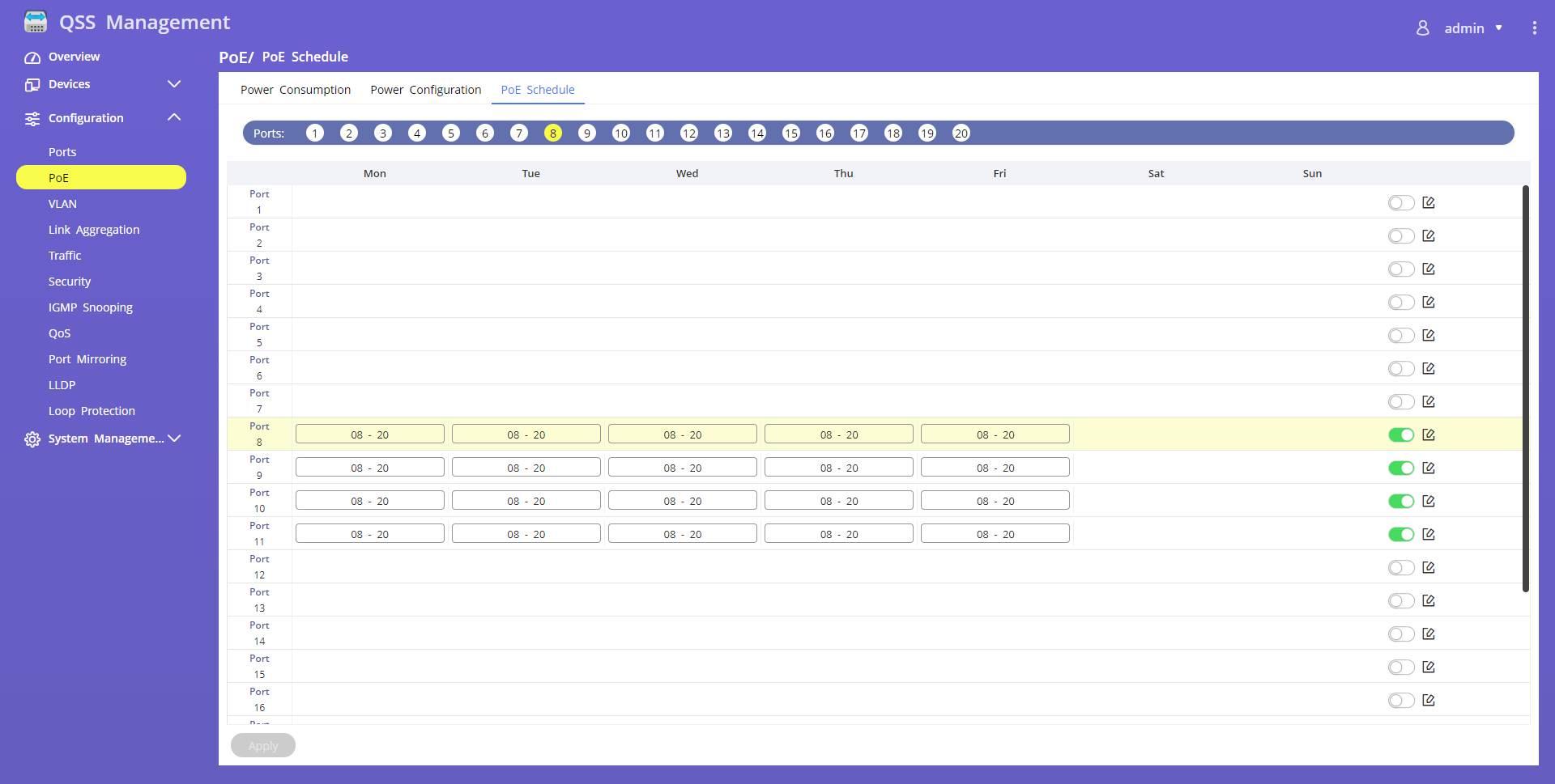
In the part of “PoE Schedule» We can configure time bands on certain days of the week, in our case we have configured the band from 8:00 a.m. to 8:00 p.m., that is, 12 hours with PoE enabled at the access points each day. Of course, in the case of IP cameras we will have it running all day.
In the vlan section we have created several VLANs for different uses, the main VLAN where we will connect the video surveillance cameras and the NAS that acts as NVR is VLAN 11, VLAN 13 is to connect other devices such as family PCs, and VLAN 15 is for guests , which will have minimum access permissions and bandwidth limitation per port. Thanks to the graphical user interface of this managed switch, we will be able to easily configure the different VLANs as untagged, and also as tagged. In the following image you can see the configuration of ports 8-11, which is where the WiFi access points are connected.
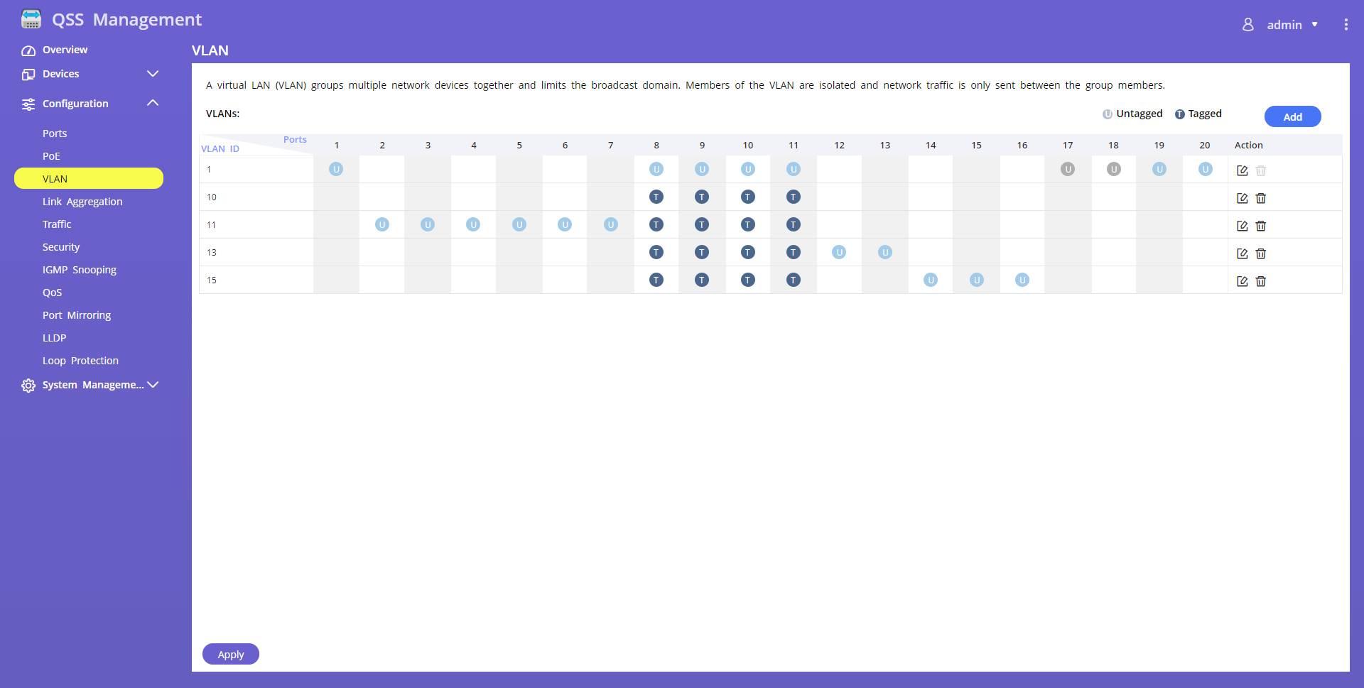
In port number 20, which is a 10GBASE-T port, it is where we have connected our main “router” that has a LAN with support for VLANs, in this way, we will not have a bottleneck when doing inter-vlan routing. In this port we must also configure all the VLANs as «tagged» since it is one of the trunk ports.
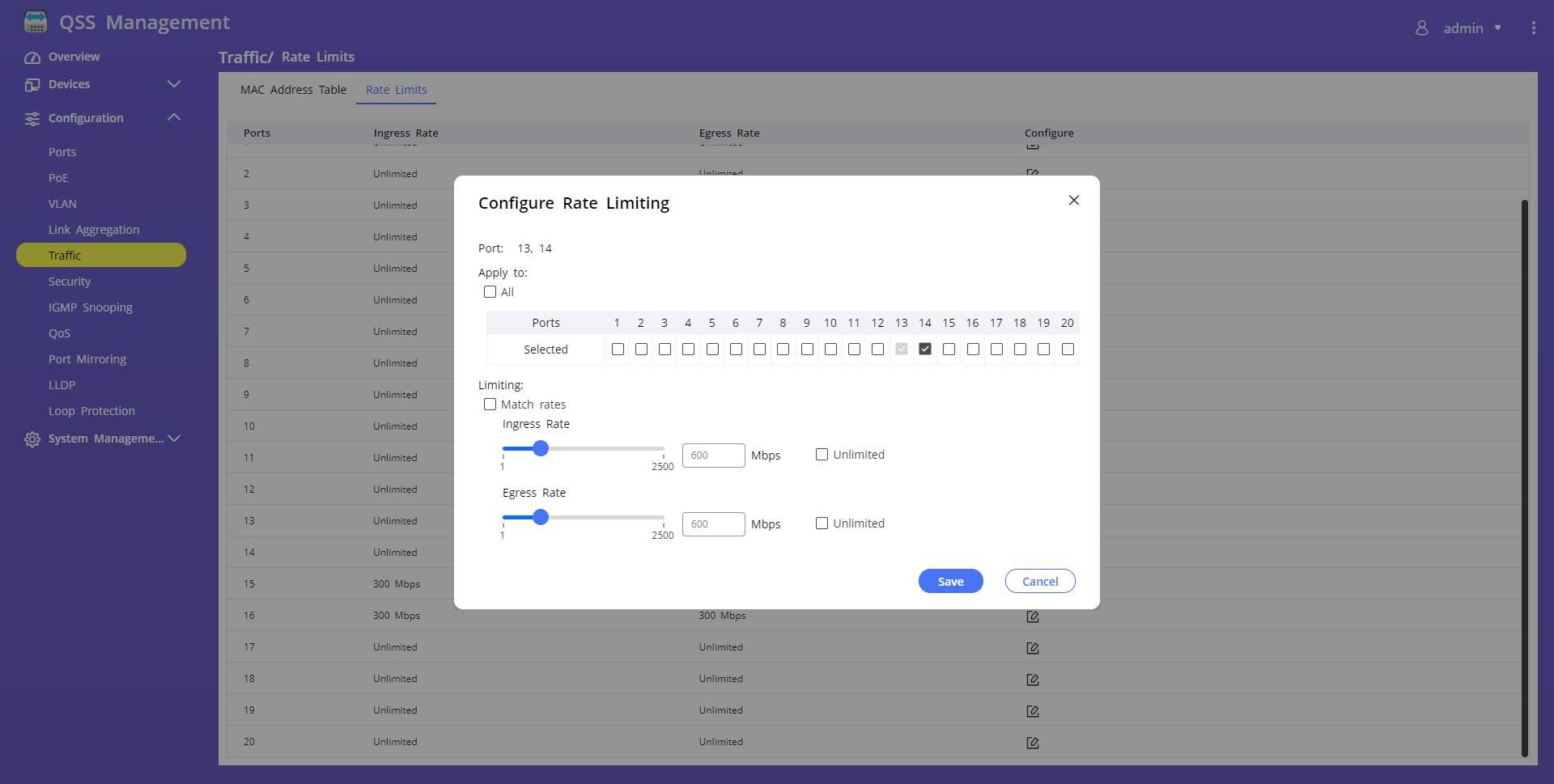
In the section of “Traffic» is where we will have the possibility to configure the bandwidth limiter of the different ports, with the configuration that we have explained before. The graphical user interface is really simple, we just select the ports we want, set a speed of “income» and another of «egress» and save the configuration.

Depending on the speed that we want to assign, we will have to configure the bandwidth limiter, and then apply it to the ports:
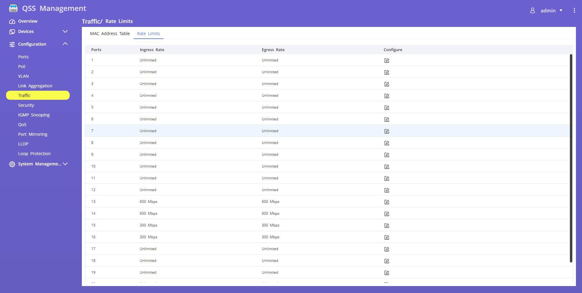
In the general settings of «Rate Limits» we have the transfer rates of each and every one of the ports:
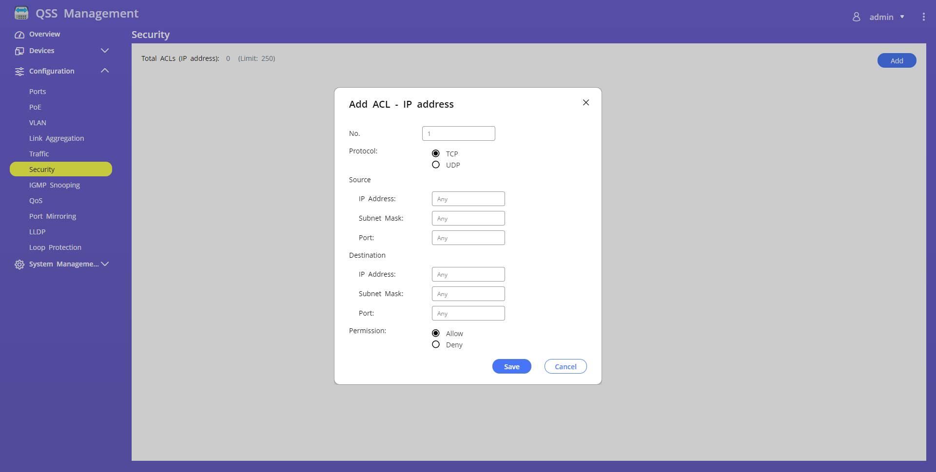
In the section of “Security» we can filter any TCP or UDP traffic at the IP level, and it also allows us to filter the corresponding ports. Although generally these options are part of the functions of the router, which is the one who does the inter-vlan routing, in certain cases we could also configure IP-based ACLs on the switch, so that the traffic does not reach the router and we block it first .
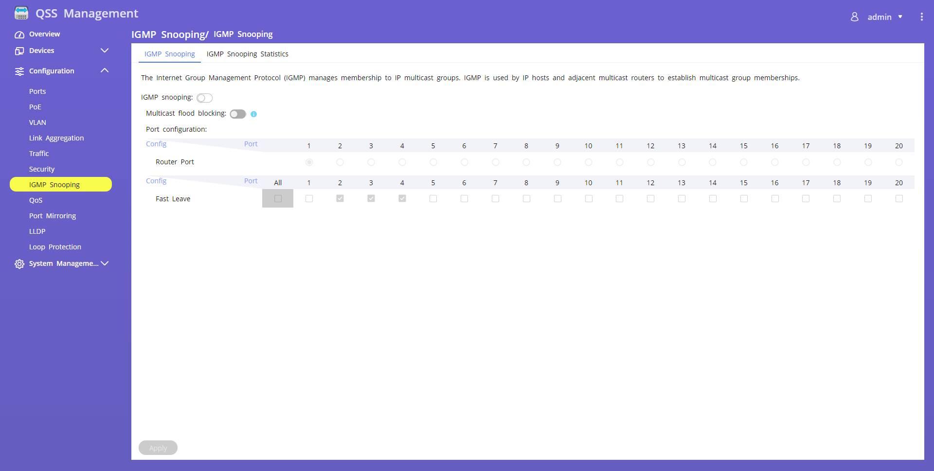
In our case, we do not use any IPTV service that uses Multicast traffic, however, this switch has IGMP Snooping functionality to properly manage this type of traffic. In the configuration menu we can activate it and block the multicast flood, in addition, we will define both the router port and the “Fast Leave” of the protocol. If you don’t use this protocol, you can safely leave it disabled.
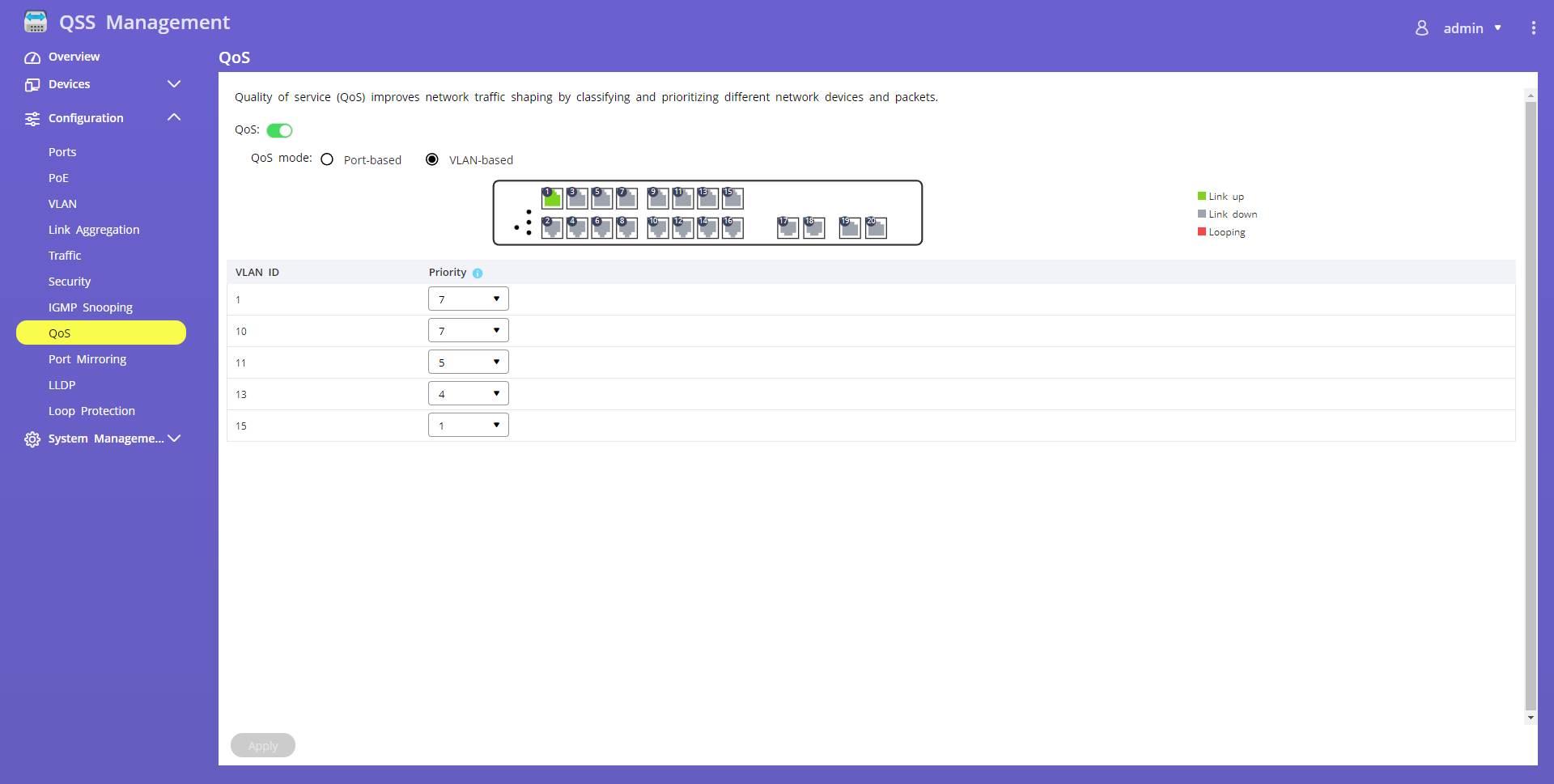
In the QoS section we can configure the priority per port or the priority per VLAN. In our case, we have configured the priority by VLANs. As you can see, we find priorities from 0 (lowest priority) to 7 (highest priority), and depending on what we need, we set these values so that in case of high traffic, the VLANs that we want always have priority.
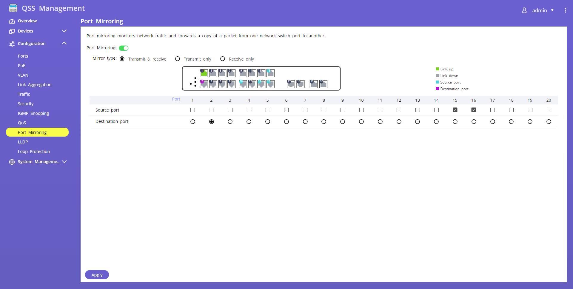
In the “Port Mirroring” section we can make the traffic of ports 14 and 15 continuously monitored. We can make the incoming and outgoing traffic of these two ports be sent directly to port number 2 where we have a PC monitoring the entire network. Although in our case we do not always have this configuration in production, we could have it whenever we want to know the network traffic that is generated in these two ports.
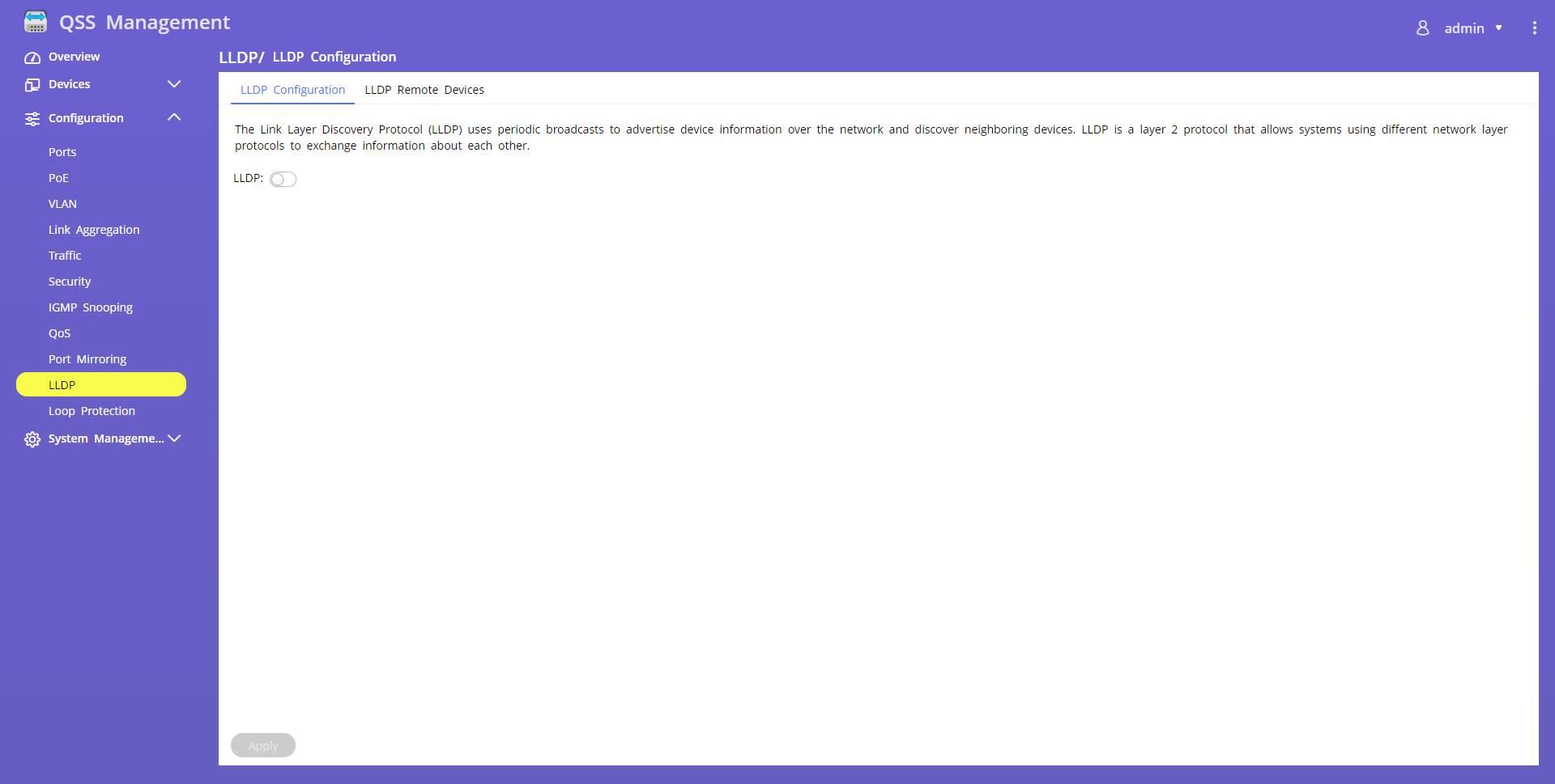
The LLDP protocol is something that we never use, but it does not have any type of configuration, we can simply activate or deactivate it, and in the “LLDP Remote Devices” tab we can see the rest of the devices that these teams also use.
This switch does not have STP or RSTP, fundamental protocols for switches and that will be available in version 2.0.0 of this switch that will be released soon. We currently have the “Loop Protection” functionality that allows us to avoid loops at the link layer level in the switch itself. In this way, if we leave this feature activated and connect a cable making a loop in the switch, it will automatically block the affected ports to prevent the network from going down.

In the following video you can see in detail how the different configurations are made in this manageable switch, we also give you other simple examples of operation that you can carry out:
This switch is currently for sale at a price of approximately 800 euros:
As you have seen, with this L2 managed switch we are going to be able to configure a fairly complex network segmented by VLANs, with its ACLs based on IP if we want it, and also with QoS based on VLANs or ports to prioritize the packets that travel inside the switch. This model is very interesting because its ports are 2.5G Multigigabit and we even have a total of 4 10GBASE-T ports, all the ports with an RJ-45 connector are PoE+ or PoE++, so we will have great versatility.